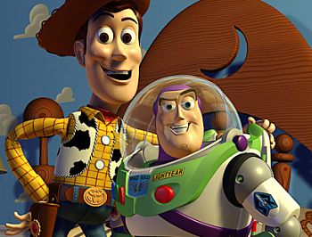
Pixar's "Toy Story", 1996
Copyright © Disney/Pixar
Computer Animation:
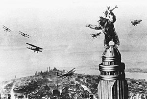
Animation has historically been produced in two ways. The first is by artists creating a succession of cartoon frames, which are then combined into a film. A second method is by using physical models, e.g. King Kong, which are positioned, the image recorded, then the model is moved, the next image is recorded, and this process is continued.
In either case, hand-drawn cel animation or stop-motion animation, the process is repetitive and time-consuming.
|
|
| Willis O'Brien's "King Kong", 1933 |
Pixar's "Toy Story", 1996 |
3D computer animation uses a rendering machine to draw successive frames wherein some aspect of the image is varied. For a simple animation this might be just moving the camera, or the relative motion of objects in the scene. This is analogous to the second technique described above, i.e., using physical models.
More sophisticated computer animation can move the camera and/or the objects in more interesting ways, e.g. along computed curved paths, and can even use the laws of Physics to determine the behavior of objects.
A major part of animation is motion control. Early systems did not have the computational power to allow for animation preview and interactive control. Also, many early animators were computer scientists rather than artists. Thus, scripting systems were developed. These systems were used as a computer high level language where the animator wrote a script (program) to control the animation. Whereas a high level programming language allows for the definition of complex data types, the scripting languages allowed for the definition of "actors" - objects with their own animation rules.
LifeForms, an early WYSIWYG motion control editor that exported animation scripts to Swivel 3D. Below, a sample script to set up the puppet:
| ShowWork ( initpics ) ( Frame 0 ) ( Count mod 2 0 ) ( Start of Figure ) FindObject body_1 RelAtt: 0.000000 90.000008 0.000000 , FindObject r_hand_1 RelAtt: 0.000000 0.000000 0.000000 , FindObject l_shoulder_1 RelAtt: 0.000000 0.000000 0.000000 , FindObject l_thigh_1 RelAtt: 0.000000 0.000000 0.000000 , FindObject l_knee_1 RelAtt: 0.000000 0.000000 0.000000 , FindObject l_upper_arm_1 RelAtt: 0.000000 0.000000 0.000000 , FindObject l_forearm_1 RelAtt: 0.000000 0.000000 0.000000 , FindObject r_shoulder_1 RelAtt: 0.000000 0.000000 0.000000 , FindObject back_1 RelAtt: 0.000000 0.000000 0.000000 , FindObject r_upper_arm_1 RelAtt: 0.000000 0.000000 0.000000 , FindObject r_forearm_1 RelAtt: 0.000000 0.000000 0.000000 , FindObject l_hand_1 RelAtt: 0.000000 0.000000 0.000000 , FindObject r_foot_1 RelAtt: 0.000000 0.000000 0.000000 , FindObject r_thigh_1 RelAtt: 0.000000 0.000000 0.000000 , FindObject r_knee_1 RelAtt: 0.000000 0.000000 0.000000 , FindObject l_foot_1 RelAtt: 0.000000 0.000000 0.000000 , FindObject neck_1 RelAtt: 0.000000 0.000000 0.000000 , FindObject head_1 RelAtt: 0.000000 0.000000 0.000000 , FindObject body_1 ( RelScale: 670.000000 , ) FindObject body_1 RelPos: 0.000000 -34.882202 0.000000 , ( End of Figure ) EffectsRender ( WritePics ) ( 0 ) ( That's all folks!!! ) |
Motion Capture:
Motion capture is the recording of human body movement (or other movement) for
immediate or delayed analysis and playback. The information captured can be
as general as the simple position of the body in space or as complex as the
deformations of the face and muscle masses. Motion capture for computer character
animation involves the mapping of human motion onto the motion of a computer
character.
From Hypergraph, a puppet animated by motion capture data.
Optical Tracking
Optical trackers typically use small markers attached to the body - either flashing
LEDs or small reflecting dots - and a series of two or more cameras focused
on the performance space. A combination of special hardware and software pick
out the markers in each camera's visual field and, by comparing the images,
calculate the three-dimensional position of each marker through time. The technology
is limited by the speed at which the makers can be examined (thus affecting
the number of positions per second that can be captured), by occlusion of the
markers by the body, and by the resolution of the cameras - specifically for
their ability to differentiate markers close together. Early systems could track
only a dozen or so markers at a time. More recent systems can track several
dozen at once. Occlusion problems can be overcome by the use of more cameras,
but even so, most current optical systems require manual post-processing to
recover trajectories when a marker is lost from view.
![]()
Optical tracking system from Vicon Motion Systems.
top of page
Kinematics
The study of the time-related properties of motion, such as position, velocity,
and acceleration, independent of the underlying forces that produce the motion.
Articulated figure
A structure that consists of a series of rigid links connected at joints, frequently
only revolute or rotary joints in computer animation.
End effector
The free end of a chain of links, e.g. a hand at the end of an arm.
Motion Control Methods (MCM)
Geometric - keyframe techniques
Physically based - using physical dynamics
Behavioral - individual and as a group
We can characterize each type by the type of information of primary importance in animating an object, especially an articulated figure. For a keyframe system this is the angle of each of the joints. In a forward kinematics system the motion of all the joints is explicitly set by the animator, i.e., for a human, the animator would move the shoulder, upper arm, elbow, forearm, and hand. In inverse kinematics the animator moves only the end effector and the system computes the corresponding position of the rest of the chain of links.
 |
 |
|
Poser, from Creative Labs, uses inverse kinematics to
pose articulated figures.
|
|
For Geometric MCMs the primary information is geometric, e.g. coordinate positions, angles, etc. For physically based MCMs, that are driven by physical laws, the primary information is the set of physicals characteristics of the system, e.g. mass, moments of inertia, stiffness (spring force constants), etc. For Behavioral systems the primary information is the set of behaviors that motivate the system.
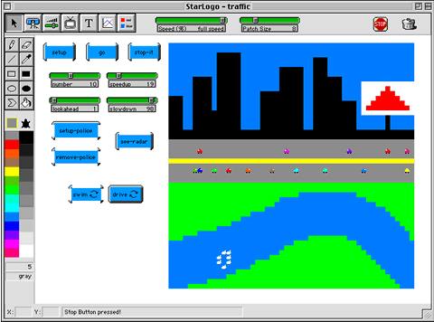
StarLogo, from MIT, scripts behaviors for actors on screen to simulate everything from the flocking patterns of migrating birds to traffic flows. Below, a sample script from a traffic simulation:
| to drive if breed = rights [ifelse (count-turtles-at 1 0) > 0 ;if there is a turtle 1 space ahead, decelerate [setspeed speed-of one-of-turtles-at 1 0 decelerate] [ifelse lookahead = 2 ;if lookahead=2, check 2 spaces ahead also [ifelse (count-turtles-at 1 0) > 0 [setspeed speed-of one-of-turtles-at 2 0 decelerate] [accelerate]] ;else accelerate [accelerate]] if speed < 0.01 [setspeed 0.01] ;also adjust speed based on SpeedLimit and radar if speed > SpeedLimit [setspeed SpeedLimit] if radar = true [setspeed .10] jump speed] if breed = lefts [ifelse (count-turtles-at (-1) 0) > 0 ;if there is a turtle 1 space ahead, decelerate [setspeed speed-of one-of-turtles-at (-1) 0 decelerate] [ifelse lookahead = 2 ;if lookahead=2, check 2 spaces ahead also [ifelse (count-turtles-at (-2) 0) > 0 [setspeed speed-of one-of-turtles-at (-2) 0 decelerate] [accelerate]] ;else accelerate [accelerate]] if speed < 0.01 [setspeed 0.01] ;also adjust speed based on SpeedLimit and radar if speed > SpeedLimit [setspeed SpeedLimit] if radar = true [setspeed .10] jump speed] end to accelerate setspeed (speed + (speedup / 10000)) end to decelerate setspeed speed - (slowdown / 1000) end |
In the situation where the animator has all the control of the actor and the actor is unaware of its environment, there is no real-time control but only batch level control, e.g. keyframes. Currently, this is the dominant form of computer animation. Geometrics and Kinematics, both forward and inverse, fall into this category. A good method to get realistic motion is rotoscopy (motion capture), where sensors attached to real actors are used to provide coordinates for input to the synthetic actors.
![]()
Wireless motion tracker from Ascension Technology.
Types of 3D models
Implicit Functions can be used to define some models that will be rendered by Ray Tracing. An example of this is a sphere, that can be defined by its position in space (X, Y, Z) and its radius (R).
The polygon mesh data structure is the most common and oldest modeling method for computer graphics.
 |
 |
Bezier curves were developed by Pierre Bezier for designing Renault automobile bodies. Bezier curves use 4 input points with the tangent vectors at the end points being determined by line segments.
For a B-spline, the curve does not neccessarily pass through any control point, but it is continuous at the curve segment end points. Therefore, a B-spline curve is "smoother" than Bezier curves.
The use of Particle systems is a way of modeling fuzzy objects, such as fire, clouds, smoke, water, etc. These don't have smooth well-defined surfaces and are non-rigid objects, i.e., they are dynamic and fluid. Particle systems differ in three ways from "normal" representations for image synthesis:
1. An object is not represented by a set of primitive surface elements, e.g., polygons or patches, but as clouds of primitive particles that define its volume.
2. A particle system is not a static entity, its particles change form and move. New particles are created and old particles are destroyed.
3. An object represented by a particle system is not deterministic, its shape and form is not completely specified. Stochastic processes are used to create and change an object's shape and appearance.
Particle systems are an example of stochastic procedural modeling, similar to fractals, and have some of the same advantages, such as the following:
1. Complex systems can be created with little human effort.
2. The level of detail can be easily adjusted. For example, if a particle system object is in the distance, then it can be modeled to low detail (few particles), but if it is close to the camera, then it can be modeled in high detail (many particles).
A particle system is a collection of many minute particles that model some object. For each frame of an animation sequence the following steps are performed:
1. New particles are generated
2. Each new particle is assigned its own set of attributes
3. Any particles that have existed for a predetermined time are destroyed
4. The remaining particles are transformed and moved according to their dynamic
attributes
5. An image of the remaining particles is rendered Since the creation and attributes
of the particles are procedural, these can be the results of other computations,
e.g. from science or engineering.
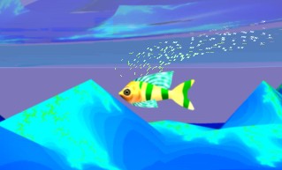
A particle system provides the illusion of bubbles for this animation.
Rendering
Ray Tracing is a global illumination based rendering method. It traces rays of light from the eye back through the image plane into the scene. Then the rays are tested against all objects in the scene to determine if they intersect any objects. If the ray misses all objects, then that pixel is shaded the background color. Ray tracing handles shadows, multiple specular reflections, and texture mapping in a very easy straight-forward manner.
Note that ray tracing, like scan-line graphics, is a point sampling algorithm. We sample a continuous image in world coordinates by shooting one or more rays through each pixel. Like all point sampling algorithms, this leads to the potential problem of aliasing, which is manifested in computer graphics by jagged edges or other nasty visual artifacts.
In ray tracing, a ray of light is traced in a backwards direction. That is, we start from the eye or camera and trace the ray through a pixel in the image plane into the scene and determine what it hits. The pixel is then set to the color values returned by the ray.
Scan line graphics has historically been the most popular method for graphics rendering. The reason for this is that it is the only method for 2D graphics and it is the fastest rendering method for 3D graphics. More recently, ray tracing is increasingly popular as a rendering technique, but most systems still use scan line rendering, or at least have a scan line option rendering option.
The central problem in scan -line rendering is scan conversion, i.e., converting from a mathematical model of an image to a framebuffer image.
Shading
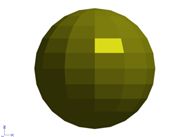
In the Constant shading model we compute one shade or color for the entire object, e.g., there really is no shading being done.
The simplest shading model is the faceted model. You compute only one intensity (color shade) per polygon. The light vector, L is computed as the vector between any point on the polygon, e.g. a vertex, and the light source position. Generally only the two term illumination model (ambient plus diffuse reflection) is used with faceted shading. Faceted shading is simple and quick but not very realistic, the facets are easily seen since there may be sharp color discontinuities at the polygon edges.
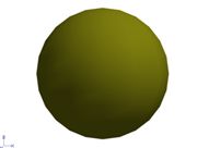
The second shading model, Gouraud shading, computes an intensity for each vertex and then interpolates the computed intensities across the polygons. Gouraud shading performs a bi-linear interpolation of the intensities down and then across scan lines. It thus eliminates the sharp changes at polygon boundaries.
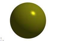
The third shading model, Phong shading, is similar to Gouraud shading except that the Normals are interpolated. Thus, the specular highlights are computed much more precisely than in the Gouraud shading model.
 |
 |
 |
|
Flat shaded.
|
Goraud shaded.
|
Phong shaded.
|
Surface mapping
Many real life surfaces are not just colored but also have textures and patterns. Many also have small or large surface displacements or bumps, gouges, etc. Texture mapping is used to simulate these surfaces and thus make images more realistic. Two techniques can be used to achieve the impression of natural colors, textures, and appearances:
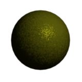
Texture Mapping is the addition of a separately defined texture or pattern to a surface (e.g., wall-paper on wall). This does not affect the "smoothness" of a surface but only changes its color patterns.
Bump Mapping is roughening the surface of an object without actually displacing the surface. The surface may look as if it actually has bumps but this is an illusion.
 |
 |
|
Texture map.
|
Bump map.
|